How to
fit an IIS electronic ignition on a on 1000 or 1200 engine (here a SFC
1000 120 engine)
(Click on the
pictures to enlarge)
Section
1 Mechanical Fitting details.
1) Disconnect battery negative first.
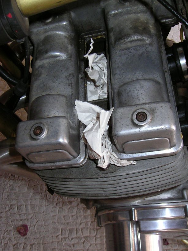
2) Remove Spark Plugs, use cloth in holes to stop parts falling in.
3) Remove Fuel Tank 4) Remove Timing side cover
5) Rotate Crank Shaft and Bring TDC mark on case to crankshaft Rotor TDC mark
check for actual TDC on cylinder 1 ( Left cylinder.....closest to timing side
)
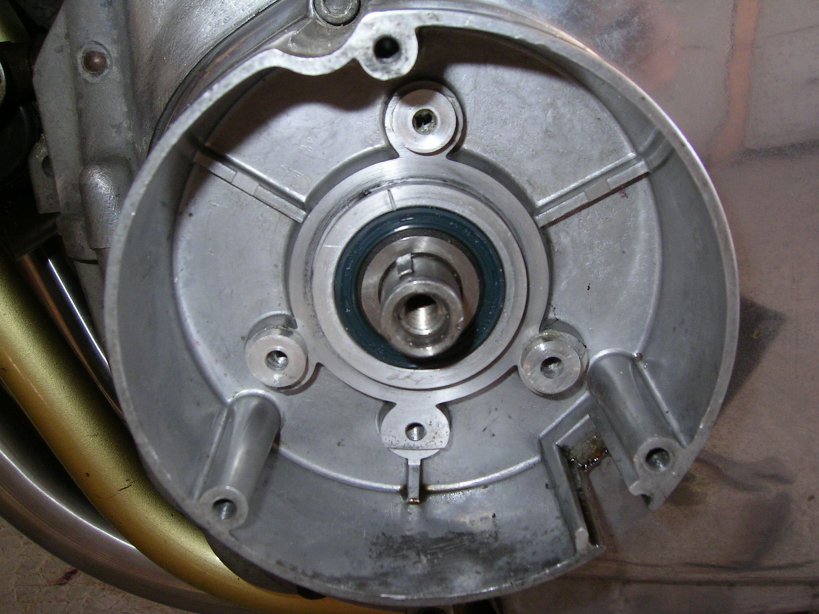
6) Remove Bosch Trigger Plate as one unit
7) Remove Impulse Cam/Rotor on Crankshaft, check for TDC on cylinder 1 if last
operation moved the Crank Shaft.
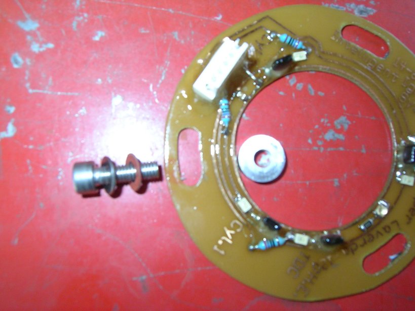
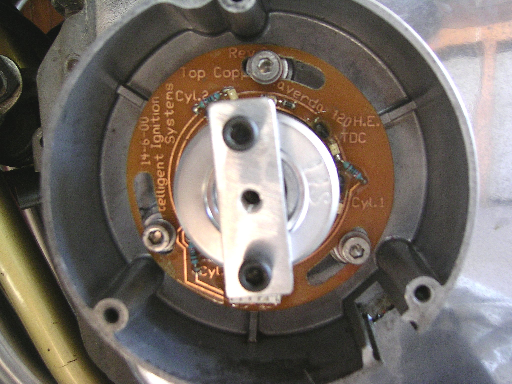
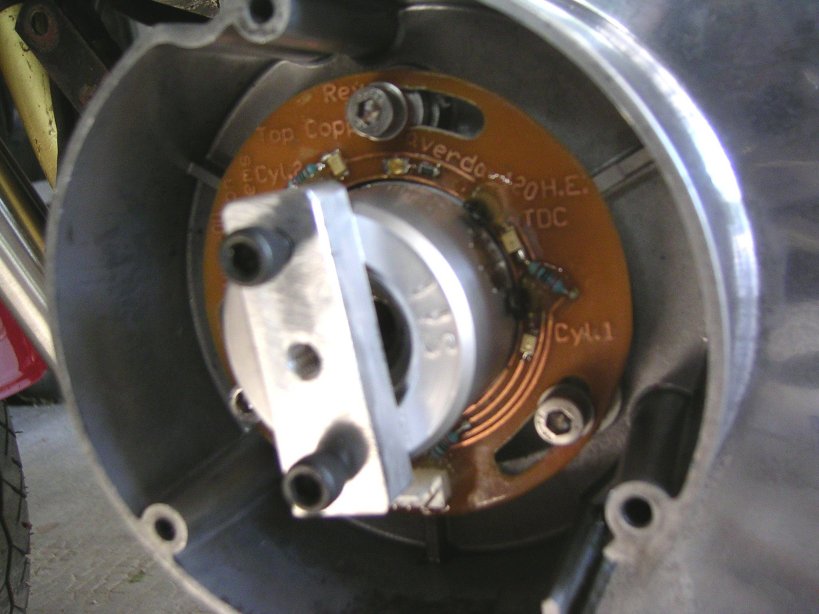
8) Fit New Shaft Encoder ( Green or Clear printed circuit board ) to the Engine
using the following order:- 5 mm Screw - Fibre Washer - Green or Clear PCB-4.7m/m
spacer.
9) For HALL EFFECT Encoder. Fit New Magnetic Rotor Assembly to the Crank Shaft,
include the Woodruff key. A removeable nut drive is supplied to assist crank
rotation it is removed when no longer required during the install Hall Effect
Rotor Removeable nut drive
10) No longer used.
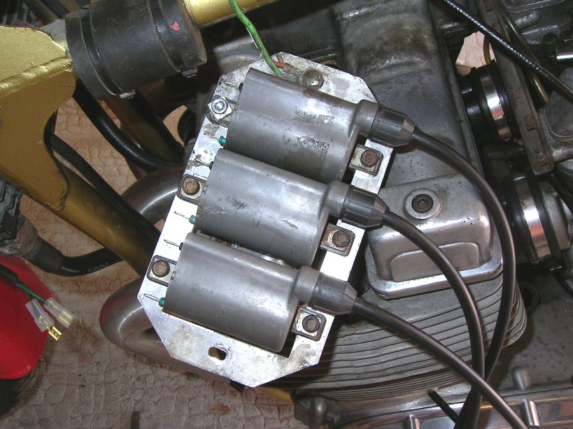
11) Fit the new supplied cable harness. The cable with the white connector goes
to the encoder the rest go to the coils.
Disconnect the ballast resistors and remove them from the top of the coils,
NipponDenso use ballasts supplied by Bosch,
Motoplat use no ballast resistors. Using the Wiring Harness and Connector data
sheet connect the coils for the correct firing
sequence. See also Diagram 2.
12) Fit the BLACK wire to the BATTERY Negative terminal, NOT FRAME DIRECT! Fit
the RED wire to the Orange wire
disconnected from the coils common wire this is now the supply +12Volt for the
module. See Wiring Harness and Connector
data sheet. UNIT DAMAGE will result if there is a short circuit from earth/frame/Supply
to the following Module/coil wires BLUE,
GREEN, YELLOW check your connections!!!! If a fuse clears then there is a problem
with the wiring do not replace fuse until you
have cleared the wiring fault. UNDER NO Circumstances should the Mauve/Purple
tacho wire be connected to the ignition coils
directly or indirectly. It only drives the electronic tacho, disconnect the
tacho from any coil connection you may have if you
use the modules tacho mauve wire. Failure to observe the above will almost certainly
damage the module.
NOTE! The ignition module fires in a sequence of 1-2-3 ALWAYS! therefore any
engine firing sequence is done at the COIL END!
This may seem confusing but it is quit simple to use once the connections are
established.
See Harness Wiring Detail.
Fit the white connector to the shaft encoder board. Taking care not to damage
the wires.
Reconnect the Battery Negative terminal to the engine/frame New spark plugs
are a cheap tune up! we recommend NGKB8ES.
Fit spark plugs to all three ignition coil HT leads and leave them touching
the engine frame and in a position so that they
can be seen. Never leave the cylinder spark plug holes open place some clean
rag into the opening to stop foreign bodies going
into the cylinder chamber.
Electrical Test and Diagnostics
Fit spark plugs to the ignition coil HT leads, resting on the engine case
so they are visible. a small amount of anti seize copper compound ( grease )
makes plug removal and fitting less prone to
damaging the threads. Auto suppliers have this product or RS Components product
number 557 073.
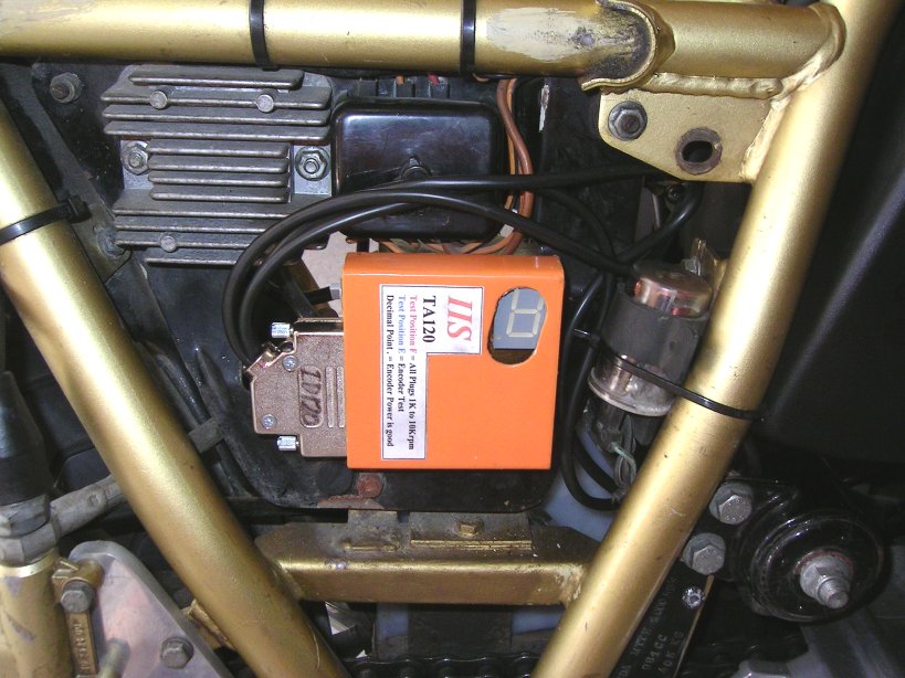
Connect the Ignition Module to the harness and switch on the ignition.
On the module there is a Yellow light that should be on, and an Orange light
on the encoder board, if not, there is a wiring
problem. If ok then turn off the ignition and if not done previously, fit spark
plugs to the ignition coil HT leads and leave them
touching the engine frame.
On the module rotate the pointer on the switch to position F see Photo 2 or
Yellow Switch F Switch on ignition there should be
sparks on all the spark plugs, if so you are doing great! if not all are firing
then there is a simple wiring mistake.
Note; The Electronic Tacho and spark plugs will indicate a chronometric spark
rate starting at 1000rpm increasing in
1000rpm steps until 10,000rpm is reached. This cycle takes about 30 seconds
to complete.
Any missing sparks ( misfiring ) at the higher spark rate indicates suspect
plugs or coils...a very handy test to help locate misfiring engines and also
can be used to " burn clean " fouled plugs to save removal of tank and plugs
when a plug fuel/oil fouls.
We use discarded spark plugs with the earth " tab " broken away giving about
a 5m/m spark gap, this gives an approximate
condition for a sparkplug/cylinder under compression, all our modules support
this spark gap at 10,000rpm if you see misfiring at
any point then check for at least 12V available to the module, if ok then the
coil/HT leads/plug caps/sparkplugs are suspect.
Email us for tech help if required.
It will then cycle again until position F is DEselected, If your Tacho indicates
any error during this test, then the error is in the
Tacho.
Switch off ignition by using the Kill Switch if Ok then turn off ignition switch.
Switch on Kill switch.
Help in setting TDC
Rotate Module switch to position E and turn on ignition.
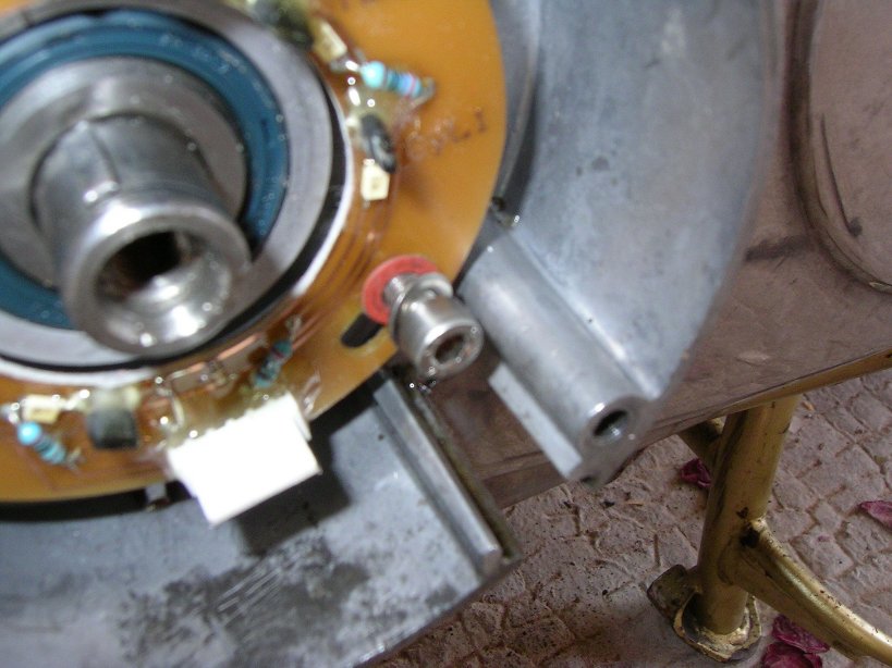
With the crank shaft at TDC cylinder 1 the rotor magnet should be just to the
right of the TDC Sensor Switch on the encoder board.
This is checked by using the Red led next to he TDC switch or as well as the
letter "c" on the Main Ignition Module Digital Display,
being ON or OFF, if the number "1" is displayed then you are probably too far
to the right and cylinder 1 is firing its spark plug.
Rotate the whole Encoder Board to the RIGHT to show the correct "c" or to get
the RED light to come on continuously, if the display
shows "c"on all the time then rotate the encoder to the LEFT untill it goes
off.
The above procedure is setting the REFERENCE Top Dead Center (TDC) for the whole
ignition system, any error here will give the
wrong signals to the ignition module with poor results the most likely outcome,
take the time to get this right.
Hall Effect at TDC We have found it to be very precise with just the slightest
of pressure on the crank shaft giving a Red led on
the Encoder Board ON Light going to OFF when the pressure is released when at
TDC.
The firing sequence can now be checked by rotating the back wheel ( or using
the supplied bolt on "key" attached to the impulse
rotor ) in the direction towards the front wheel and confirm the correct sequence
ie Left-centre-right ).
The first cylinder to fire after the TDC reference is the Centre cylinder its
spark plug should spark and the Display show "2"
and the Red led lights on the Encoder board. The middle spark plug will fire
at 1000rpm switch, no other plugs should fire at
this point, if the other plugs are firing at the same time then there is a wiring
fault ( short circuit between BLUE or YELLOW
or GREEN or you are not using suppressor spark plug caps/wiring...naughty ).
Continue with the rotation until the correct
sequence is confirmed. The display will show "3" for the right cylinder and
its spark plug will fire. Switch the ignition off and rotate the switch on the
module to the 0 position. That completes the calibration procedure, with the
spark plugs fitted to the cylinders, fuel on, ignition on, starter engaged,
there will be a movement of the Digital display bar from bottom to top bar or
top to bottom bar,
depending on where the crank starts from. At any rate the display will change
from a number display ( the current curve selection
number ) to the rising bar display mode when the crank shaft begins to rotate.
The yellow light stays on all the time that the ignition
is switched on, and the engine should fire. The IDLE may have to be adjusted
to about 1000RPM after warming up. This is indicated
by the middle Bar on the Digital Module Display.
Setting the Idle Speed
The Tacho as fitted to most Motorcycles is an indicator not a scientific Instrument
ie; its accuracy is poor.
On the module 1000rpm is indicated by the Red Middle Light Bar on. Less than
1000rpm the lower bar is on 1000 to Rev limit
is indicated by the Upper Light Bar on
Ne
pas oublier d'obturer les trous de bougies
Dévisser
les vis du stator Bosch
Déposer
le faisceau de stator
Préparer
le stator IIS et les vis, les rondelles dans cet ordre
Coller
les entretoises (qui viennent sous le stator) avec un peu de graisse
Fixer
le stator, sans serrer les vis pour l'instant
Stator
en place
Monter
le rotor (ici avec l'outil destiné à pouvoir le tourner)
Au
bon calage sur le PMH, le plot magnétique doit être juste
à droite du pick-up de PMH
Monter
le faisceau de l'IIS en réutilisant le passe-fil
Les
bobines Tek03 montent parfaitement en place des Motoplat ou des ND
Pour
le test d'étincelles, mettre les bougies à la masse